Filter
Filters are SVG's mechanism to create sophisticated effects.
Filters are defined by the <filter> element, which should be put in the <defs> section of your SVG, and you must give the filter an id so you can reference it elsewhere.
(You would reference the filter using the filter attribute.)
How filter primitive works
Between the <filter> tags, goes a list of primitives (the <fe*> tags). Primitives are basic operations like blurring, adding a lighting effect, etc.
They take in images specified by the in and/or in2 attributes, and store the result in a name specified by the result attribute.
Primitive global attributes
All primitives accept these attributes:
result— name for the filter primitive result; the name can be referenced in theinorin2attribute of another primitive.x,y,width,height— position and dimension of the filter primitive viewport (to "crop out" the filter primitive layer)
Primitive in and in2 attributes
For in or in2, you can specify one of the following:*
SourceGraphic— use the graphic elements that use the<filter>SourceAlpha— use the graphic elements that use the<filter>, but only use the alpha channel (the colors will become gray)- The name from a
resultattribute
The default value is SourceGraphic for first filter primitive, otherwise it's the result of the previous filter primitive.
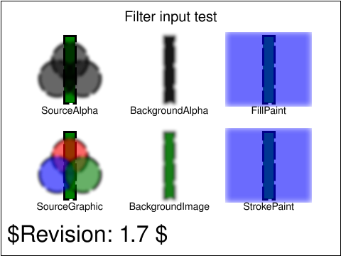
in values. The image consists a group of 3 RGB circles on top of a vertical rectangle. The blur filter effect is applied on the group of RGB circles. (Source: W3)(*) I omit BackgroundImage, BackgroundAlpha, FillPaint, and StrokePaint as I don't understand what the spec is saying, and it's not consistent on Chrome and Firefox. (See the in attribute test)
Filter SVG element
<filter>
x— x coordinate offset of the filtery— y coordinate offset of the filterwidth— width the filterheight— height of the filterfilterUnits— defines the coordinate system for attributesx,y,width,height; specifyuserSpaceOnUse(use viewport/absolute coordinate) orobjectBoundingBox(use the bounding box of the element that references the filter, with coordinate values ranging from 0 to 1)primitiveUnits— defines the coordinate system for the filter primitives (the children of<filter>); specifyuserSpaceOnUse(use viewport/absolute coordinate) orobjectBoundingBox(use the bounding box of the element that references the filter, with coordinate values ranging from 0 to 1)
<svg xmlns="http://www.w3.org/2000/svg" width="240" height="120">
  <defs>
    <filter id="filter-blur">
      <feGaussianBlur stdDeviation="5"/>
    </filter>
  </defs>
  <circle cx="60" cy="60" r="50" fill="orange" />
  <circle cx="180" cy="60" r="50" fill="orange" filter="url(#filter-blur)" />
</svg>Primitive SVG elements
result, x, y, width, height.<feBlend>
Composes objects together and apply a blending mode.
in— first input (the "top" image)in2— second input (the "bottom" image)mode— the blending mode to use; specify:normal,darken,lighten,multiply,screen,overlay,color-dodge,color-burn,hard-light,soft-light,difference,exclusion,hue,saturation,color, orluminosity
<svg xmlns="http://www.w3.org/2000/svg" width="100" height="100">
  <defs>
    <filter id="filter-blend">
      <feFlood result="floodFill" x="0" y="0" width="100%" height="100%" flood-color="red" flood-opacity="1" />
      <feBlend in="SourceGraphic" in2="floodFill" mode="multiply" />
    </filter>
  </defs>
  <image
    x="0" y="0" width="100" height="100"
    href="/res/unsplash/andrew-ridley-jR4Zf-riEjI-unsplash.jpg"
    preserveAspectRatio="xMidYMid slice"
    filter="url(#filter-blend)"
  />
</svg><feColorMatrix>
Changes colors based on a transformation matrix. (The final RGBA value will be clamped between 0 and 1.)
in— the input imagetype—matrix,saturate,hueRotate, orluminanceToAlphavalues— depends ontype(if you specifytypeother thanmatrix, it will construct the matrix based on the value oftypeandvalues):- for
type="matrix": input the first four rows of the matrix (ignore the last row because it's a constant) - for
type="saturate": input a single real number from 0 to 1 - for
type="hueRotate": input a single real number (representing the degrees) - for
type="luminanceToAlpha":valuesis not required
- for
<svg xmlns="http://www.w3.org/2000/svg" width="100" height="100">
  <defs>
    <filter id="filter-color-matrix">
      <!-- remove red color component -->
      <!-- note that we don't input the last row of the matrix -->
      <feColorMatrix
        in="SourceGraphic"
        type="matrix"
        values="
          0 0 0 0 0
          0 1 0 0 0
          0 0 1 0 0
          0 0 0 1 0
        " />
    </filter>
  </defs>
  <image
    x="0" y="0" width="100" height="100"
    href="/res/unsplash/andrew-ridley-jR4Zf-riEjI-unsplash.jpg"
    preserveAspectRatio="xMidYMid slice"
    filter="url(#filter-color-matrix)"
  />
</svg><feComponentTransfer>
Performs remapping for each color component. It allows operations like brightness adjustment, contrast adjustment, color balance, or thresholding (MDN).
in— the input image
<feComponentTransfer> expects you to provide these "transfer function" children elements: <feFuncR>, <feFuncG>, <feFuncB>, <feFuncA>. Each transfer function element accepts:
type— defines how to map each color component to . specify one of:identity—table— use linear interpolation using values given intableValues.tableValuescontains values (each ranging from 0 to 1), specifying the "start" and "end" values for evenly sized interpolation regions. A color would fall into one of these interpolation regions; you would then perform a linear interpolation using the "start" and "end" values of the region.discrete— use the step function using values given intableValues.tableValuescontains values (each ranging from 0 to 1), specifying a step function consisting of evenly sized steps. A color would fall into one of these "steps", you just use thetableValuesvalue representing the step.linear— expects you to giveslopeandinterceptattributes, representing and respectively. Then, .gamma— expects you to giveamplitude,exponent, andoffsetattributes, representing , , and respectively. Then, .
<svg xmlns="http://www.w3.org/2000/svg" width="100" height="100">
  <defs>
    <filter id="filter-component-transfer">
      <!-- use linear transformation -->
      <feComponentTransfer in="SourceGraphic">
        <feFuncR type="linear" slope="1" intercept="0" />
        <feFuncG type="linear" slope="2" intercept="-0.5" />
        <feFuncB type="linear" slope="2" intercept="0" />
      </feComponentTransfer>
    </filter>
  </defs>
  <image
    x="0" y="0" width="100" height="100"
    href="/res/unsplash/andrew-ridley-jR4Zf-riEjI-unsplash.jpg"
    preserveAspectRatio="xMidYMid slice"
    filter="url(#filter-component-transfer)"
  />
</svg><feComposite>
Performs Porter–Duff compositing operations.
in— first input (the "top" image)in2— second input (the "bottom" image)operator—over,in,out,atop,xor,lighterorarithmetic(default isover)k1,k2,k3,k4— required whenoperator="arithmetic". With and representing pixel channel values ofinandin2respectively, the result pixel channel value is given as
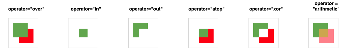
operator values (Source: Codepen)<feConvolveMatrix>
Applies a matrix convolution filter effect. Operations that can be achieved through convolution include blurring, edge detection, sharpening, embossing and beveling (MDN).
A convolution combines pixels in the input image with its neighboring pixels to produce a resulting image. The convolution matrix (the "convolution kernel") is an orderY () by orderX () matrix; together with divisor , bias , targetX , targetY , yield the calculation:
in— the input imageorder— size of the kernel matrix (default is 3); if you specify two numbers (e.g.3 4), the first number representsorderX(number of columns), and the second number respresentsorderY(number or rows)kernelMatrix— space-separated list of numbers, representing the kernel matrixdivisor— represents in the equation above (default is sum of all values inside thekernelMatrix)bias— represents in the equation above (default is 0)targetX— offsets the x positioning of the kernel matrix relative to the target pixel (default is centered around the target pixel, i.e. )targetY— offsets the y positioning of the kernel matrix relative to the target pixel (default is centered around the target pixel, i.e. )edgeMode— how to handle the case near the edge of the input image; specifyduplicate(default),wrap, ornonepreserveAlpha— a value offalse(default) indicates that the convolution will apply to all channels (including alpha channel)
<svg xmlns="http://www.w3.org/2000/svg" width="100" height="100">
  <defs>
    <filter id="filter-convolve-matrix">
      <!-- use linear transformation -->
      <feConvolveMatrix kernelMatrix="
        0 -1 0
        -1 3 -1
        0 -1 0
      " />
    </filter>
  </defs>
  <image
    x="0" y="0" width="100" height="100"
    href="/res/unsplash/andrew-ridley-jR4Zf-riEjI-unsplash.jpg"
    preserveAspectRatio="xMidYMid slice"
    filter="url(#filter-convolve-matrix)"
  />
</svg><feDiffuseLighting>
Lights an image using the alpha channel as a bump map. (Bump mapping is a "texture mapping technique in computer graphics for simulating bumps and wrinkles on the surface of an object," Wikipedia.)
in— the input imagesurfaceScale— height of surface for an alpha value of 1diffuseConstant— (diffuse reflection constant) in Phong reflection modellighting-color— color of the light
<feDiffuseLighting> expects you to provide the light sources using <fePointLight>, <feDistantLight>, or <feSpotLight> children elements.
<!-- https://developer.mozilla.org/en-US/docs/Web/SVG/Element/feDiffuseLighting -->
<svg xmlns="http://www.w3.org/2000/svg" width="480" height="140">
  <defs>
    <!-- the light source is a fePointLight element -->
    <filter id="filter-diffuse-fePointLight">
      <feDiffuseLighting
        in="SourceGraphic" result="light"
        lighting-color="white">
        <fePointLight x="160" y="60" z="20" />
      </feDiffuseLighting>
      <feComposite
        in="SourceGraphic" in2="light"
        operator="arithmetic" k1="1" k2="0" k3="0" k4="0"
      />
    </filter>
    <!-- the light source is a fePointLight element -->
    <filter id="filter-diffuse-feDistantLight">
      <feDiffuseLighting
        in="SourceGraphic" result="light"
        lighting-color="white">
        <feDistantLight azimuth="240" elevation="30" />
      </feDiffuseLighting>
      <feComposite
        in="SourceGraphic" in2="light"
        operator="arithmetic" k1="1" k2="0" k3="0" k4="0"
      />
    </filter>
    <!-- the light source is a feSpotLight source -->
    <filter id="filter-diffuse-feSpotLight">
      <feDiffuseLighting
        in="SourceGraphic" result="light"
        lighting-color="white">
        <feSpotLight
          x="420" y="20" z="30"
          pointsAtX="420" pointsAtY="80" pointsAtZ="0"
          limitingConeAngle="20"
        />
      </feDiffuseLighting>
      <feComposite
        in="SourceGraphic" in2="light"
        operator="arithmetic" k1="1" k2="0" k3="0" k4="0"
      />
    </filter>
  </defs>
  <!-- No light is applied -->
  <text text-anchor="middle" x="60" y="22">
    No Light
  </text>
  <circle cx="60" cy="80" r="50" fill="green" />
  <!-- the light source is a fePointLight element -->
  <text text-anchor="middle" x="180" y="22">fePointLight</text>
  <circle cx="180" cy="80" r="50" fill="green" filter="url(#filter-diffuse-fePointLight)" />
  <!-- the light source is a feDistantLight element -->
  <text text-anchor="middle" x="300" y="22">feDistantLight</text>
  <circle cx="300" cy="80" r="50" fill="green" filter="url(#filter-diffuse-feDistantLight)" />
  <!-- the light source is a feSpotLight source -->
  <text text-anchor="middle" x="420" y="22">feSpotLight</text>
  <circle cx="420" cy="80" r="50" fill="green" filter="url(#filter-diffuse-feSpotLight)" />
</svg><feSpecularLighting>
Lights an image using the alpha channel as a bump map. (Bump mapping is a "texture mapping technique in computer graphics for simulating bumps and wrinkles on the surface of an object," Wikipedia.)
in— the input imagesurfaceScale— height of surface for an alpha value of 1specularConstant— (specular reflection constant) in Phong reflection modelspecularExponent— larger value means more "shiny"lighting-color— color of the light
<feDiffuseLighting> expects you to provide the light sources using <fePointLight>, <feDistantLight>, or <feSpotLight> children elements.
<!-- https://developer.mozilla.org/en-US/docs/Web/SVG/Element/feSpecularLighting -->
<svg xmlns="http://www.w3.org/2000/svg" height="100" width="100">
  <defs>
    <filter id="filter-specular">
      <feSpecularLighting
        result="specOut"
        specularExponent="20" lighting-color="#ff0000">
        <fePointLight x="25" y="25" z="100"/>
      </feSpecularLighting>
      <feComposite
        in="SourceGraphic" in2="specOut" result="compositeLight"
        operator="arithmetic" k1="0" k2="1" k3="1" k4="0"
      />
      <feComposite
        in2="SourceGraphic" in1="compositeLight"
        operator="in"
      />
    </filter>
  </defs>
  <circle cx="50" cy="50" r="40" style="filter:url(#filter-specular)"/>
</svg><feDisplacementMap>
Use the pixel values from in2 to spatially displace the pixels from in:
where is the input image (in), is the destination, is the scale, and are the component values of the channel designated by the xChannelSelector and yChannelSelector.
in— input image to be displacedin2— input image that governs how we displaceinscale— displacement scale factor (see above)xChannelSelector— which channel to use to displace the pixels ininalong the x-axis; specifyR,G,B, orA(default isA)yChannelSelector— which channel to use to displace the pixels ininalong the y-axis; specifyR,G,B, orA(default isA)
<!-- https://developer.mozilla.org/en-US/docs/Web/SVG/Element/feTurbulence -->
<svg xmlns="http://www.w3.org/2000/svg" width="200" height="200" >
  <defs>
    <filter id="filter-splotch">
    <!-- create noise -->
    <feTurbulence
      type="turbulence" baseFrequency="0.05"
      numOctaves="2" result="turbulence" />
    <!-- displacement map -->
    <feDisplacementMap
      in2="turbulence" in="SourceGraphic"
      scale="50" xChannelSelector="R" yChannelSelector="G" />
  </filter>
  </defs>
  <circle cx="100" cy="100" r="90" fill="blue" filter="url(#filter-splotch)" />
</svg><feDropShadow>
Creates a drop shadow of the input image.
dx— x offset of the drop shadowdy— y offset of the drop shadowstdDeviation— the standard deviation for the blur operation in the drop shadowflood-color— color of the shadowflood-opacity— opacity of the shadow
<svg xmlns="http://www.w3.org/2000/svg" width="100" height="100" >
  <defs>
    <!-- allow the blur to bleed outside by increasing the width/height -->
    <filter id="filter-shadow" width="150%" height="150%">
      <feDropShadow dx="5" dy="5" stdDeviation="5" flood-color="red" flood-opacity="0.5" />
    </filter>
  </defs>
  <circle cx="50" cy="50" r="30" fill="pink" filter="url(#filter-shadow)" />
</svg><feFlood>
Fills the filter subregion with a color.
flood-color— color of the fillflood-opacity— opacity of the fill
<svg xmlns="http://www.w3.org/2000/svg" width="100" height="100">
  <defs>
    <filter id="filter-flood" filterUnits="userSpaceOnUse">
      <feFlood
        x="10" y="10" width="80" height="80"
        flood-color="green" flood-opacity="0.5"
      />
    </filter>
  </defs>
  <use style="filter: url(#filter-flood);" />
</svg><feGaussianBlur>
Applies a gaussian blur.
in— the input imagestdDeviation— the standard deviation for the blur operationedgeMode— how to handle the case near the edge of the input image; specifyduplicate,wrap, ornone(default)
<svg xmlns="http://www.w3.org/2000/svg" width="100" height="100">
  <defs>
    <filter id="filter-gaussian-blur">
      <feGaussianBlur stdDeviation="2" />
    </filter>
  </defs>
  <image
    x="0" y="0" width="100" height="100"
    href="/res/unsplash/andrew-ridley-jR4Zf-riEjI-unsplash.jpg"
    preserveAspectRatio="xMidYMid slice"
    filter="url(#filter-gaussian-blur)"
  />
</svg><feImage>
Fetches the image data from an external source and provides the pixel data as output (if the external source is an SVG image, it is rasterized).
href— URL to the imagepreserveAspectRatio— seepreserveAspectRatio(default isxMidYMid meet)
<svg xmlns="http://www.w3.org/2000/svg" width="100" height="100">
  <defs>
    <filter id="filter-image">
      <feImage href="/res/unsplash/andrew-ridley-jR4Zf-riEjI-unsplash.jpg" />
    </filter>
  </defs>
  <rect x="10%" y="10%" width="80%" height="80%" style="filter: url(#filter-image);"/>
</svg><feMerge>
Allows you to show/merge multiple results at once.
<feMerge> expects you to put <feMergeNode> elements as its children. (<feMergeNode> only accepts the attribute in.)
<!-- https://developer.mozilla.org/en-US/docs/Web/SVG/Element/feMerge -->
<svg xmlns="http://www.w3.org/2000/svg" width="100" height="100">
<defs>
  <filter id="feOffset" x="-40" y="-20" width="100" height="200">
    <feOffset in="SourceGraphic" dx="30" dy="30" />
    <feGaussianBlur result="blur" stdDeviation="5" />
    <!-- Otherwise you can't display the offset+blurred image
    <!-- and the original image at once -->
    <feMerge>
      <feMergeNode in="blur" />
      <feMergeNode in="SourceGraphic" />
    </feMerge>
  </filter>
</defs>
<rect x="20" y="20" width="60" height="60" style="stroke: #000000; fill: green; filter: url(#feOffset);" />
</svg><feMorphology>
Erodes or dilates the input image (thickens or thins it).
in— the input imageoperator—erode(default) ordilateradius— radius for the operation
<div id="morphology-example">
  <!-- filter definition -->
  <svg xmlns="http://www.w3.org/2000/svg" style="height: 0">
    <defs>
      <filter id="filter-erode">
        <feMorphology operator="erode" radius="1" />
      </filter>
      <filter id="filter-dilate">
        <feMorphology operator="dilate" radius="1" />
      </filter>
    </defs>
  </svg>
  <!-- sample texts -->
  <p>Normal text</p>
  <p class="thin">Thinned text</p>
  <p class="thick">Fattened text</p>
</div>#morphology-example p {
margin: 0;
font-family: Arial, Helvetica, sans-serif;
font-size: 2em;
}
/* You can refer to the SVG filter ID from CSS! */
#morphology-example .thin {
filter: url(#filter-erode);
}
#morphology-example .thick {
filter: url(#filter-dilate);
}Normal text
Thinned text
Fattened text
<feOffset>
Offsets the input image.
in— the input imagedx— offset in the x axisdy— offset in the y axis
<feTile>
Fill a target rectangle with a repeated, tiled pattern of an input image. The effect is similar to the one of a <pattern>.
in— the input image
<svg xmlns="http://www.w3.org/2000/svg" width="200" height="200">
  <defs>
    <filter id="filter-tile" x="0" y="0" width="100%" height="100%">
      <!-- idk why you need to write <feTile /> twice, -->
      <!-- otherwise the image is not tiled (displayed only once) -->
      <feTile in="SourceGraphic" x="50" y="50" width="100" height="100" />
      <feTile />
    </filter>
  </defs>
  <image
    x="0" y="0" width="200" height="200"
    href="/res/unsplash/lucas-benjamin-wQLAGv4_OYs-unsplash.jpg"
    preserveAspectRatio="xMidYMid slice"
    filter="url(#filter-tile)"
  />
</svg><feTurbulence>
Creates an image using Perlin turbulence function.
type— specifyfractalNoiseorturbulence(default)baseFrequency— the base frequency parameter(s) for the noise function (if two numbers are provided, the first number represents the base frequency for the x axis, and the other for the y axis)numOctaves— the number of octaves for the noise function (the higher this number is, the more natural the noise looks, but requires more computation)seed— the starting number for the pseudo random number generatorstitchTilesdefines how the Perlin Noise tiles behave at the border; specifynoStitch(default) orstitch
<!-- https://developer.mozilla.org/en-US/docs/Web/SVG/Element/feTurbulence -->
<svg xmlns="http://www.w3.org/2000/svg" width="200" height="200" >
  <defs>
    <filter id="filter-turbulence">
      <feTurbulence type="turbulence" baseFrequency="0.05" numOctaves="2" />
    </filter>
  </defs>
  <!-- the shape does not matter -->
  <!-- everything will be turned into noise -->
  <circle cx="100" cy="100" r="90" fill="blue" filter="url(#filter-turbulence)" />
</svg>Light source elements
<fePointLight>
x,y,z— position of light
<feSpotLight>
x,y,z— position of lightpointsAtX,pointsAtY,pointsAtZ— to where the light is pointingspecularExponent— bigger means bricghterlimitingConeAngle— angle in degrees between the spot light axis (between the light source and the point to which it is pointing); no light is projected outside the cone.
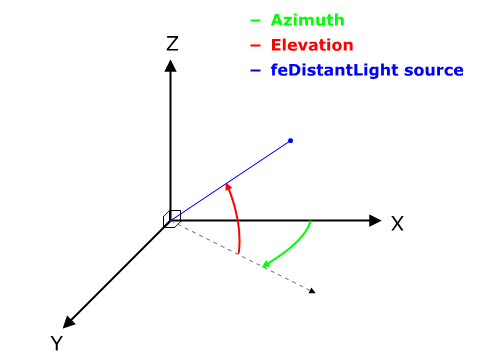
<feDistantLight>
azimuth— the direction angle for the light source on the xy-plane (clockwise), from the positive x-axis. (Controls which side/edge of the shape is reflecting the light.)elevation— the direction angle for the light source from the XY plane towards the Z-axis.
References
- Filter effects (MDN) — https://developer.mozilla.org/en-US/docs/Web/SVG/Tutorial/Filter_effects
- <filter> (MDN) — https://developer.mozilla.org/en-US/docs/Web/SVG/Element/filter
- in (MDN) — https://developer.mozilla.org/en-US/docs/Web/SVG/Attribute/in
- <feBlend> (MDN) — https://developer.mozilla.org/en-US/docs/Web/SVG/Element/feBlend
- <feColorMatrix> (MDN) — https://developer.mozilla.org/en-US/docs/Web/SVG/Element/feColorMatrix
- 15.10 Filter primitive ‘feColorMatrix’ (W3C) — https://www.w3.org/TR/SVG11/filters.html#feColorMatrixTypeAttribute
- <feComponentTransfer> (MDN) — https://developer.mozilla.org/en-US/docs/Web/SVG/Element/feComponentTransfer
- 9.7.1. Transfer function feFuncR (W3C) — https://drafts.fxtf.org/filter-effects/#feFuncRElement
- <feComposite> (MDN) — https://developer.mozilla.org/en-US/docs/Web/SVG/Element/feComposite
- 9.8. Filter primitive feComposite (W3C) — https://drafts.fxtf.org/filter-effects/#feCompositeElement
- <feConvolveMatrix> (MDN) — https://developer.mozilla.org/en-US/docs/Web/SVG/Element/feConvolveMatrix
- 15.13 Filter primitive ‘feConvolveMatrix’ (W3C) — https://www.w3.org/TR/SVG11/filters.html#feConvolveMatrixElementTargetXAttribute
- <feDiffuseLighting> (MDN) — https://developer.mozilla.org/en-US/docs/Web/SVG/Element/feDiffuseLighting
- <feSpecularLighting> (MDN) — https://developer.mozilla.org/en-US/docs/Web/SVG/Element/feSpecularLighting
- <feDisplacementMap> (MDN) — https://developer.mozilla.org/en-US/docs/Web/SVG/Element/feDisplacementMap
- <feDropShadow> (MDN) — https://developer.mozilla.org/en-US/docs/Web/SVG/Element/feDropShadow
- <feFlood> (MDN) — https://developer.mozilla.org/en-US/docs/Web/SVG/Element/feFlood
- <feGaussianBlur> (MDN) — https://developer.mozilla.org/en-US/docs/Web/SVG/Element/feGaussianBlur
- <feImage> (MDN) — https://developer.mozilla.org/en-US/docs/Web/SVG/Element/feImage
- <feMerge> (MDN) — https://developer.mozilla.org/en-US/docs/Web/SVG/Element/feMerge
- <feMorphology> (MDN) — https://developer.mozilla.org/en-US/docs/Web/SVG/Element/feMorphology
- <feOffset> (MDN) — https://developer.mozilla.org/en-US/docs/Web/SVG/Element/feOffset
- <feTile> (MDN) — https://developer.mozilla.org/en-US/docs/Web/SVG/Element/feTile
- <feTurbulence> (MDN) — https://developer.mozilla.org/en-US/docs/Web/SVG/Element/feTurbulence
- 9.21. Filter primitive feTurbulence (W3C) — https://drafts.fxtf.org/filter-effects/#feTurbulenceElement